Oct 3, 2026
Flight Controller v1
Unboxing the MPU6050 IMU sensor
Understanding how the MPU6050 is constructed and principle of working.
Field note
This is my personal documentation. Please fact check before using it for your personal references as it may contain some mistakes.
The way how a MPU6050 sensor is constructed is on the top of something called as the "Proof of mass" which is simply a defined mass suspended via, let's say - microscopic springs.
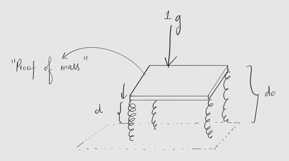 We know that
Also by Hooke's law
Equating both, we get
And thats how the sensor measures acceleration, with three know variables ie: the spring constant, the mass which is defined during fabrication of the IC, and the displacement of the proof of mass. Next question? How do we find displacement? Well, what do we get when we have two parallel plates in parallel and a medium of space in between each other - a capacitor. Here the proof of mass and the surface of the silicon beneath acts like a parallel plate capacitor. Hence
Rearranging,
Equating for d in equation 3,
The earlier constructions of the accelerometers included three of these proof of mass to measure acceleration in all three axis, until after when it was redesigned with just one proof of mass.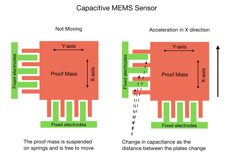
Illustration from mjwhite8119
In reality, the plates never hit the fixed electrodes, instead a reverse voltage is generated to keep the plates in place proportional to the G force experienced, which is thereby used to measure capacitance and thus acceleration.